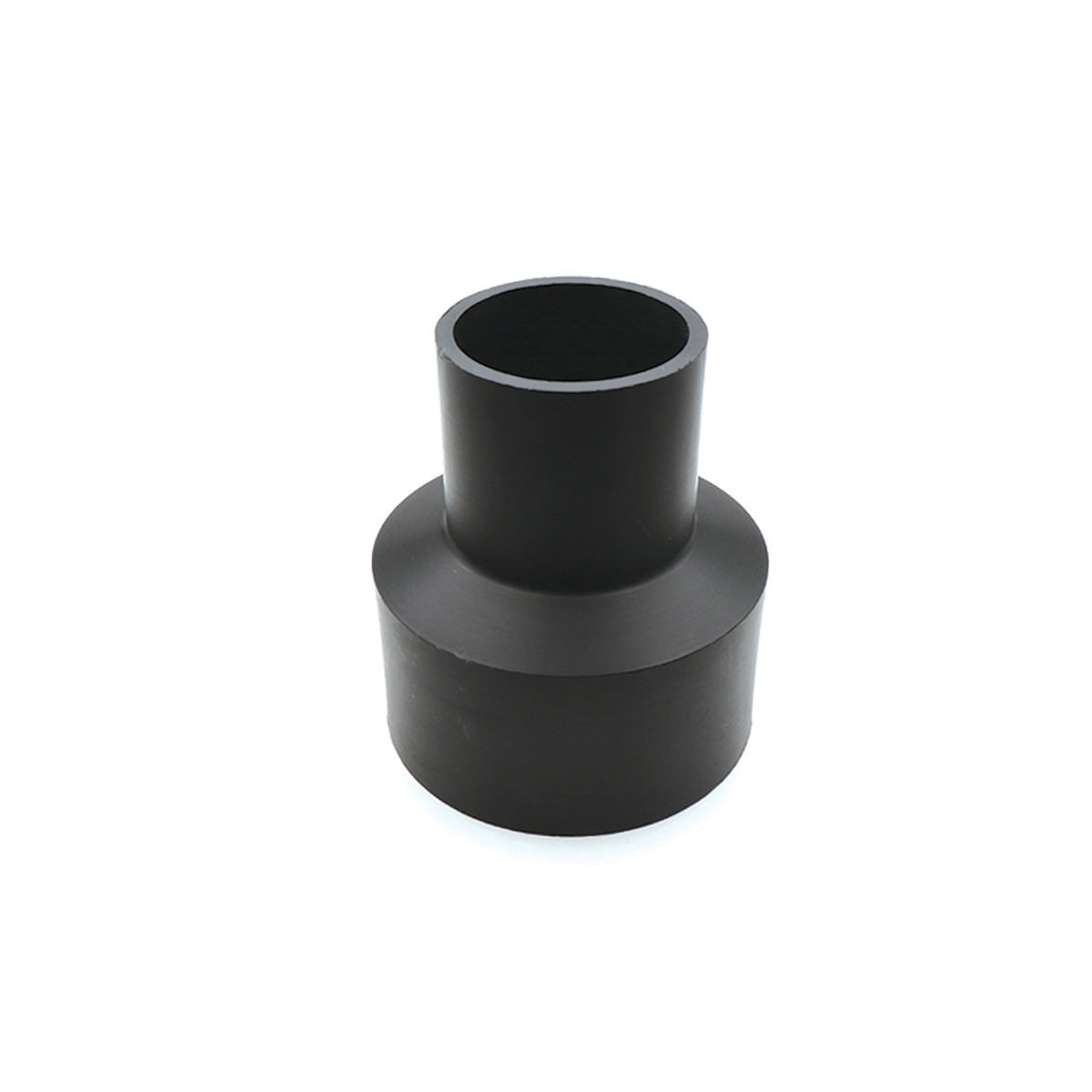
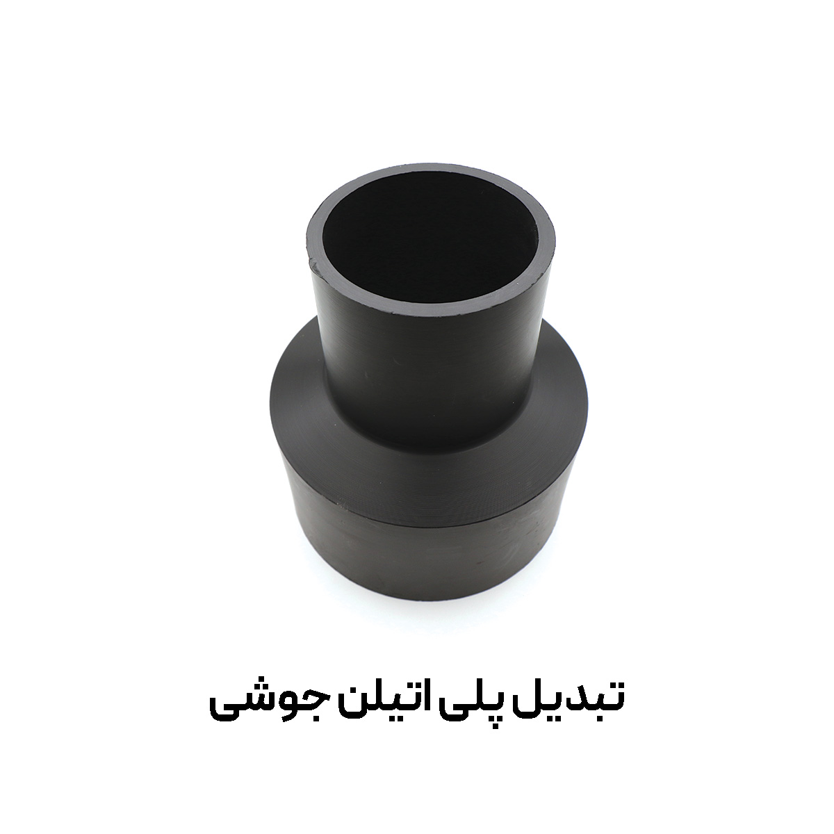
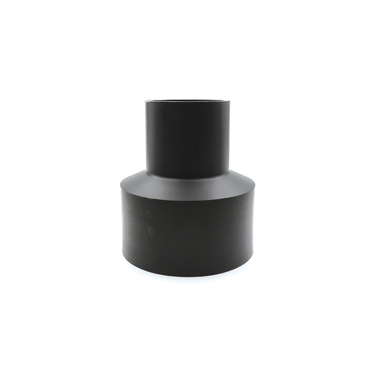
Polyethylene reducer (PE Reducer) is a reducing fitting that connects two pipes with different diameters coaxially. This part has three key lengths for measurement and quality control: Lt (overall reducer length), L1 (length of the small/outlet end), and L (length of the large/inlet end). In many drawings and catalogs, the symbol L2 is used instead of L, which refers to the same length of the inlet or large end. Below are the method for reading these dimensions and the table of nominal sizes.
Definition of Dimensions and Measurement Method
- Lt – overall reducer length: distance between the two outer ends of the part. When measuring, keep the tool parallel to the part’s axis to avoid angular error.
- L1 – length of the small end (outlet): effective length from the end of the small end to the step of diameter change. This length is important for setting preheating depth and marking the fusion line.
- L (or L2) – length of the large end (inlet): effective length from the end of the large end to the step of diameter change. This value is used when setting up the butt-fusion machine or the overlap in electrofusion.
Key Technical Notes for Selection and Installation
- Compatibility with SDR/PN: Before selecting the reducer, ensure the pipe pressure classes are equal or compatible to prevent local stresses.
- Material grade (PE100/PE80): For new water and gas networks, PE100 is more common; when mixing materials, follow the manufacturer’s instructions.
- Connection method: In butt fusion, the edges must be perfectly coaxial and aligned; in electrofusion, the lengths L1 and L/L2 determine how much of each end goes inside the coupler.
- Tolerance control: The table values are the basis for workshop QC; for minor discrepancies, refer to the manufacturer’s specified tolerances.
- Avoiding common errors: Confusing L with L1 or measuring on a warped piece can cause incomplete fusion and leakage; keep surfaces clean and flat.
Quick Guide to Symbols
| Symbol | Unit | Description |
|---|---|---|
| Lt | mm | Overall length of the PE reducer |
| L1 | mm | Length of the small end (outlet) |
| L / L2 | mm | Length of the large end (inlet); in some drawings shown as L2 |
Nominal Sizes of Polyethylene Reducer (mm)
| Nominal size (mm) | Lt (mm) | L2 (mm) | L1 (mm) |
|---|---|---|---|
| 20×32 | 118 | 41 | 45 |
| 25×32 | 118 | 41 | 45 |
| 25×40 | 118 | 41 | 45 |
| 32×40 | 125 | 50 | 45 |
| 25×50 | 134 | 59 | 48 |
| 32×50 | 125 | 58 | 48 |
| 40×50 | 129 | 62 | 51 |
| 20×63 | 131 | 61 | 30 |
| 25×63 | 132 | 61 | 43 |
| 32×63 | 142 | 60 | 40 |
| 40×63 | 133 | 57 | 49 |
| 50×63 | 131 | 55 | 56 |
| 40×75 | 148 | 67 | 46 |
| 50×75 | 148 | 66 | 55 |
| 63×75 | 143 | 67 | 58 |
| 63×90 | 139 | 71 | 51 |
| 75×90 | 151 | 69 | 64 |
| 20×110 | 151 | 77 | 41 |
| 32×110 | 155 | 78 | 42 |
| 63×110 | 167 | 77 | 54 |
| 75×110 | 167 | 82 | 64 |
| 90×110 | 210 | 91 | 64 |
| 63×125 | 158 | 85 | 54 |
| 75×125 | 214 | 91 | 77 |
| 90×125 | 214 | 91 | 77 |
| 110×125 | 152 | 74 | 63 |
| 63×160 | 212 | 76 | 87 |
| 75×160 | 212 | 76 | 87 |
| 90×160 | 212 | 76 | 87 |
| 110×160 | 151 | 101 | 83 |
| 125×160 | 227 | 94 | 70 |
| 90×180 | 236 | 95 | 70 |
| 110×180 | 265 | 112 | 86 |
| 125×180 | 265 | 112 | 86 |
| 140×180 | 285 | 133 | 87 |
| 160×180 | 245 | 112 | 79 |
| 63×200 | 263 | 112 | 82 |
| 75×200 | 263 | 112 | 82 |
| 90×200 | 263 | 112 | 82 |
| 110×200 | 260 | 114 | 85 |
| 125×200 | 248 | 101 | 88 |
| 140×200 | 285 | 133 | 88 |
| 160×200 | 285 | 133 | 88 |
| 180×200 | 285 | 133 | 88 |
| 63×225 | 287 | 115 | 80 |
| 75×225 | 287 | 115 | 80 |
| 90×225 | 287 | 115 | 80 |
| 110×225 | 287 | 115 | 80 |
| 125×225 | 287 | 115 | 80 |
| 140×225 | 287 | 115 | 80 |
| 160×225 | 287 | 115 | 80 |
| 180×225 | 286 | 142 | 91 |
| 200×225 | 286 | 142 | 91 |
| 90×250 | 285 | 120 | 85 |
| 110×250 | 285 | 120 | 85 |
| 160×250 | 287 | 115 | 80 |
| 180×250 | 299 | 126 | 96 |
| 200×250 | 286 | 142 | 91 |
| 160×315 | 486 | 150 | 95 |
| 200×315 | 390 | 154 | 96 |
| 250×315 | 390 | 154 | 96 |
| 250×355 | 260 | 95 | 120 |
| 315×355 | 260 | 95 | 120 |
| 160×400 | 470 | 190 | 105 |
| 200×400 | 470 | 190 | 110 |
| 250×400 | 470 | 190 | 117 |
| 315×400 | 470 | 190 | 126 |
| 315×450 | 325 | 120 | 120 |
| 355×450 | 325 | 120 | 120 |
| 400×450 | 325 | 120 | 120 |
| 355×500 | 325 | 120 | 120 |
| 400×500 | 325 | 120 | 120 |
| 450×500 | 400 | 101 | 101 |
| 400×560 | 400 | 101 | 101 |
| 400×630 | 400 | 101 | 101 |
| 500×630 | 400 | 101 | 101 |
| 560×630 | 400 | 101 | 101 |
Practical Recommendations for Projects
- Water and wastewater networks: To reduce pressure drop, make the diameter change near control points (valves/tanks) and use reducers with short Lt in confined spaces.
- Gas distribution and industry: Accurate selection of L1 and L/L2 together with checking end ovality leads to uniform fusion and reduces the risk of leakage.
- Storage and handling: Avoid direct sunlight and point loading on reducers; warpage can distort measurements of L1 and L/L2.
Tamam Baha supplies a range of polyethylene fittings and reducers from reputable brands and—depending on brand availability—can provide the sizes listed above. While not the only seller in the market, Tamam Baha supports customers across the region with technical advice, SDR/PN matching, and dimensional checks (Lt, L1, L/L2) before dispatch to make correct selection and safe installation easier for your projects.