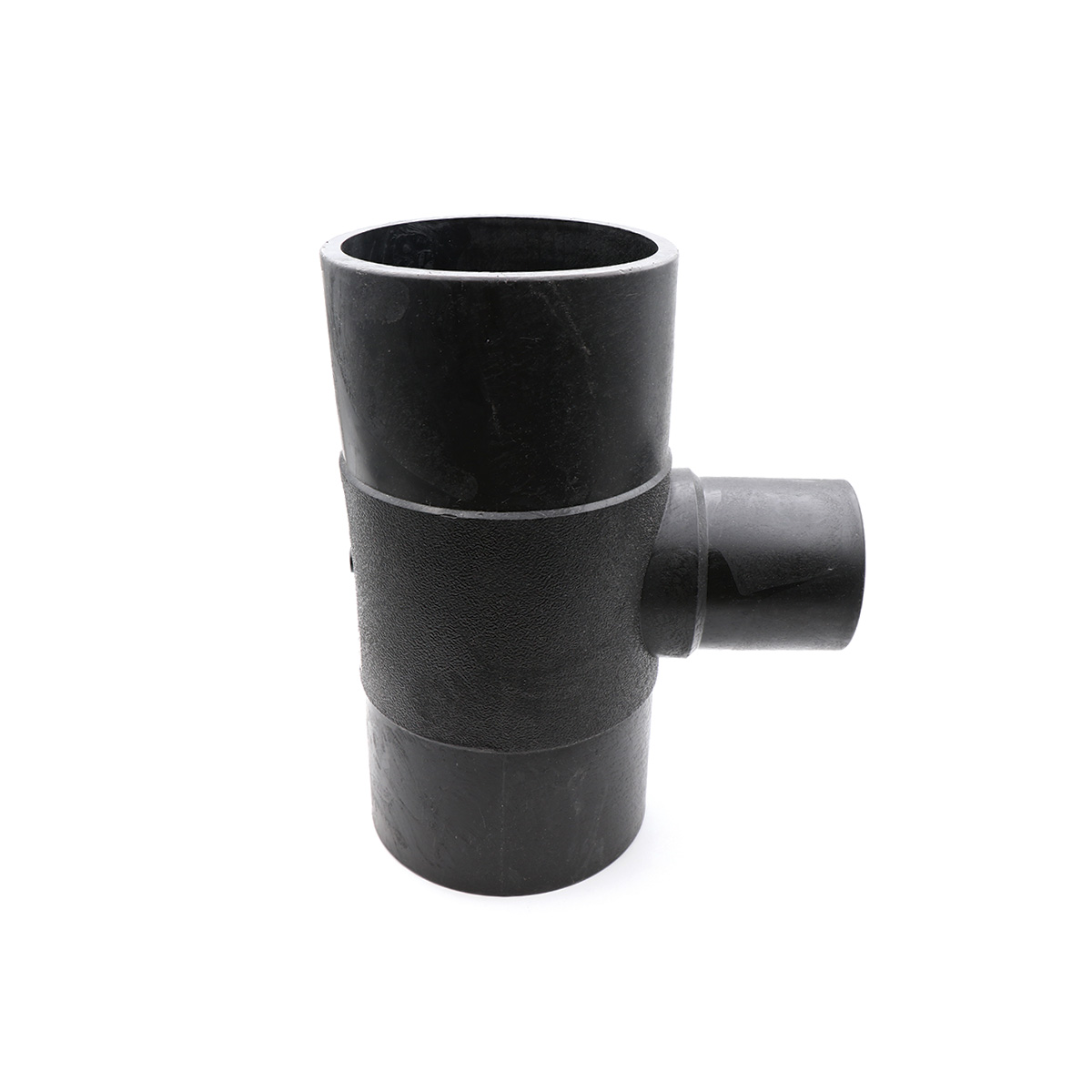
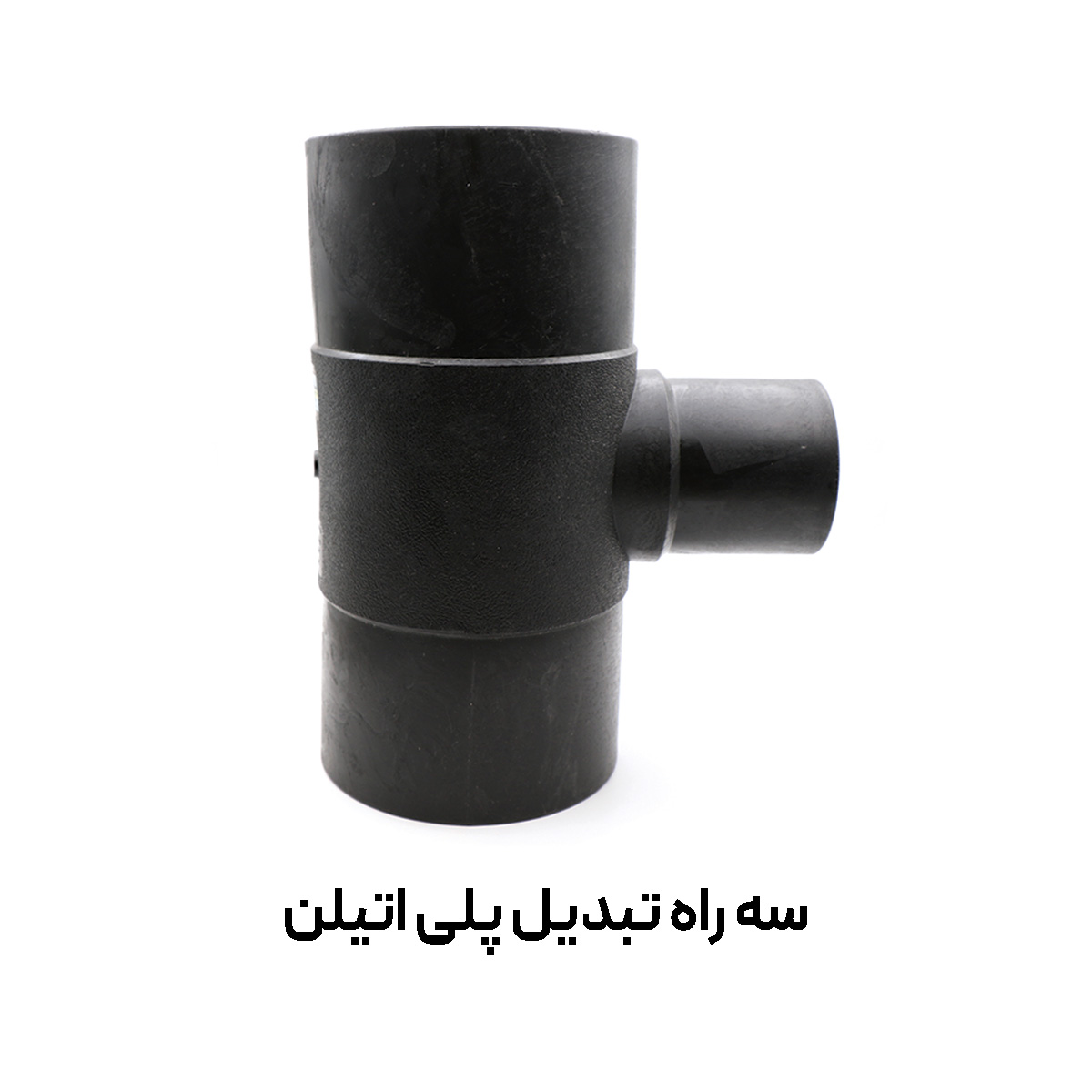
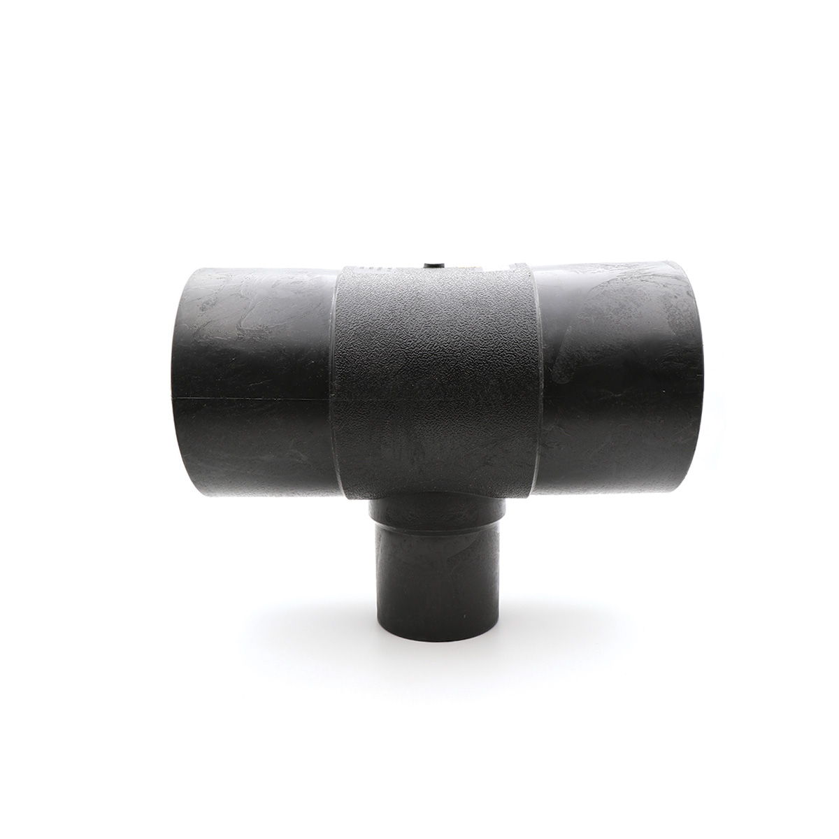
Polyethylene Reducing Tee (Reducing Tee) is one of the key fittings in pressurized piping networks that, with its three outlets, enables branching and size reduction. In this fitting, two outlets are equal-sized and colinear, while the third outlet is designed with a smaller diameter to manage flow rate and pressure in the branch. The body is produced from PE100 polyethylene and, thanks to high mechanical and chemical durability, is widely used in water supply, wastewater, oil, gas, and petrochemical services.
What is a polyethylene reducing tee?
The high-pressure welded reducing tee is an unequal PE100 fitting that is joined to the main line by two primary welding technologies—electrofusion and butt fusion. The molecular structure and suitable density of PE100 provide resistance to impact, abrasion, chemical corrosion, pressure surges, and temperature variations, ensuring reliable sealing over the service life.
Advantages and key features
- High resistance to mechanical loads, thermal stresses, and corrosive chemicals
- No rusting or rotting; suitable for humid and corrosive environments
- Lightweight with faster installation compared to metal fittings
- Low roughness coefficient and reduced pressure drop for flowing media
- Long service life and easy maintenance during operation
- Uniform sealing in welded joints, reducing leakage risk
- Compatible with sprinkler and drip irrigation systems for optimized flow control
Applications
- Urban and rural water-supply networks; transmission and distribution lines
- Firefighting systems and pressurized industrial lines
- Oil, gas, and petrochemical industries for conveying diverse fluids
- Wastewater and effluent facilities with high chemical resistance
- Agricultural irrigation networks (sprinkler and drip) for branching and pressure management
Joining methods and execution notes
Butt Fusion: Align the two faces, heat to melting temperature, then apply controlled pressure until a uniform weld bead forms.
Electrofusion: Use a coupler with an embedded heating wire; apply specified voltage and time to create a structural weld.
Key notes: Precise alignment and fixing, thoroughly clean surfaces, control weld temperature/time/pressure, allow cooling to reach final strength, and record welding parameters for quality traceability.
Dimensional guide and selection
Dimensional parameters of the reducing tee are critical for design and drafting:
- Z1: overall length of the fitting
- Z2: height from the centerline of the main run to the axis of the branch
- L1 & L2: engagement lengths for electrofusion couplers / weld ends
When selecting a size, in addition to matching the mainline and branch diameters, consider the required SDR/PN, the nature and temperature of the fluid, and the allowable pressure drop in the branch.
General technical specifications
| Item | Value/Description |
|---|---|
| Body material | High-density polyethylene PE100 |
| Joining type | Butt fusion and electrofusion welding |
| Manufacturing standard | DIN 16963 |
| Applications | Water supply, wastewater, irrigation, oil, gas, and process services |
| Features | Resistant to corrosion, impact, abrasion, and chemicals |
| Operational advantage | Reliable sealing, low weight, quick installation, long service life |
Size range and dimensions of high-pressure welded reducing tee (PE100)
| Nominal size (mm) | Z2 (mm) | Z1 (mm) | L2 (mm) | L1 (mm) |
|---|---|---|---|---|
| 32×63 | 105 | 216 | 49 | 65 |
| 40×63 | 105 | 216 | 49 | 65 |
| 50×63 | 105 | 216 | 63 | 67 |
| 40×75 | 119 | 249 | 50 | 73 |
| 50×75 | 133 | 250 | 63 | 71 |
| 63×75 | 120 | 245 | 65 | 72 |
| 50×90 | 131 | 275 | 66 | 71 |
| 63×90 | 128 | 271 | 67 | 72 |
| 75×90 | 168 | 267 | 70 | 69 |
| 50×110 | 157 | 318 | 65 | 86 |
| 63×110 | 168 | 318 | 67 | 87 |
| 75×110 | 159 | 320 | 72 | 81 |
| 90×110 | 156 | 319 | 80 | 86 |
| 50×125 | 167 | 337 | 72 | 90 |
| 63×125 | 165 | 340 | 65 | 90 |
| 75×125 | 167 | 337 | 66 | 89 |
| 90×125 | 163 | 332 | 81 | 89 |
| 110×125 | 169 | 341 | 82 | 91 |
| 75×140 | 185 | 380 | 90 | 83 |
| 90×140 | 185 | 380 | 90 | 83 |
| 110×140 | 187 | 380 | 90 | 85 |
| 125×140 | 187 | 380 | 90 | 85 |
| 63×160 | 198 | 406 | 67 | 102 |
| 75×160 | 196 | 402 | 76 | 98 |
| 90×160 | 202 | 399 | 85 | 102 |
| 110×160 | 205 | 406 | 90 | 104 |
| 125×160 | 201 | 407 | 92 | 103 |
| 63×180 | 207 | 445 | 51 | 108 |
| 90×180 | 260 | 428 | 53 | 108 |
| 110×180 | 217 | 440 | 82 | 110 |
| 160×180 | 214 | 440 | 105 | 105 |
| 63×200 | 225 | 440 | 75 | 116 |
| 75×200 | 290 | 443 | 72 | 116 |
| 90×200 | 227 | 450 | 83 | 118 |
| 110×200 | 225 | 448 | 87 | 116 |
| 125×200 | 228 | 450 | 91 | 117 |
| 160×200 | 225 | 405 | 102 | 116 |
| 63×225 | 260 | 530 | 110 | 120 |
| 75×225 | 260 | 530 | 110 | 120 |
| 90×225 | 260 | 530 | 110 | 120 |
| 110×225 | 260 | 530 | 110 | 120 |
| 125×225 | 260 | 530 | 110 | 120 |
| 160×225 | 260 | 530 | 110 | 120 |
| 63×250 | 355 | 518 | 90 | 101 |
| 90×250 | 263 | 519 | 79 | 102 |
| 110×250 | 262 | 520 | 82 | 104 |
| 125×250 | 270 | 515 | 90 | 100 |
| 160×250 | 265 | 523 | 99 | 102 |
| 200×250 | 268 | 515 | 116 | 105 |
| 90×315 | 296 | 596 | 93 | 92 |
| 110×315 | 302 | 590 | 137 | 118 |
| 125×315 | 296 | 595 | 92 | 92 |
| 160×315 | 287 | 590 | 90 | 93 |
| 200×315 | 300 | 600 | 93 | 91 |
| 225×315 | 290 | 600 | 90 | 91 |
| 250×315 | 300 | 595 | 94 | 117 |
| 90×355 | 278 | 646 | 87 | 119 |
| 110×355 | 280 | 647 | 88 | 120 |
| 125×355 | 286 | 648 | 102 | 119 |
| 160×355 | 308 | 650 | 114 | 118 |
| 200×355 | 332 | 645 | 117 | 119 |
| 225×355 | 333 | 645 | 116 | 119 |
| 250×355 | 332 | 645 | 115 | 120 |
| 160×400 | 324 | 645 | 103 | 101 |
| 200×400 | 327 | 670 | 102 | 115 |
| 250×400 | 330 | 670 | 100 | 113 |
| 315×400 | 350 | 670 | 112 | 120 |
| 200×500 | 401 | 788 | 123 | 122 |
| 225×500 | 389 | 770 | 114 | 123 |
| 250×500 | 390 | 780 | 115 | 120 |
| 315×500 | 315 | 770 | 118 | 118 |
Design and operation notes
- Hydraulic coordination: Select the branch diameter according to flow rate and allowable pressure drop so that velocity remains within standard limits.
- Anchoring and restraint: Use proper thrust restraint at direction changes and branches to control water hammer.
- Environmental conditions: For above-ground installation, protect against UV with a cover/coating or proper burial practices.
- Pressure testing: After welding and the cooling period, perform hydrostatic testing per the manufacturer’s instructions.
Brands and manufacturing quality
High-pressure polyethylene reducing tees are supplied by reputable domestic manufacturers, including Polyran and Polirod, who, using PE100 raw materials and process quality control, deliver durable products compliant with reference standards.
At the end, Tamam Baha, as a supplier of PE100 butt-welded polyethylene reducing tees, is ready to support your water-supply, irrigation, and industrial projects. While we are not the only seller, you can contact our sales team to check stock, obtain technical details, and select the appropriate size based on your project drawings.